Building a Hornby layout Power Supply
Building a permanent Hornby layout needs a power supply that can supply the electrical current to operate the locomotives, lights, signals, powered points and all the other electrical accessories. The electrical items on a permanent Hornby layout operate at a nominal 12 to 14 Volts d.c.
For best performance it is necessary to have an individual power supply for each track speed controller such that the current drawn by one locomotive cannot influence the power supply to another locomotive. The power supply built in this article is a six channel power supply, 5 for locomotive control and 1 for the electrical accessories on the layout, e.g. layout lighting.
This power supply is for use in the UK and has an input of 230V a.c. 50 Hz and an output of 6 x 14V d.c. current limited to 1.8 Amps each. The completed power supply is 300mm x 190mm x 85mm and weighs nearly 4Kg.
Caution: Mains power supplies MUST be built by qualified engineers. Mains electricity can cause serious injury and death if not handled correctly. By that same token, a qualified engineer will already know how to build a power supply for a Hornby layout so this article only exists for completeness.

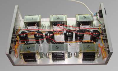
The main / large components of the power supply are positioned in the base of the box to ensure there's room for the components and for the assembly processes such as soldering and wire routing.
The 6 transformers and 6 smoothing capacitors can be seen. The transformers have a capability of 2 Amp 14 V a.c. output with a 230 V 50 Hz input. The electrolytic capacitors have a capacity of 1000 micro Farads.
The base of the power supply box is drilled so the transformers and bridge rectifiers can be bolted into position. The transformers are secured with M4 fixings and the bridge rectifiers are secured with M3 fixings.
Further holes are drilled for the output wires, and indicator LEDs. The grommet shown is used to protect the output wires.


This is a transformer with the wires soldered into position for the output, yellow for the a.c. ground reference and orange for the a.c. power. This will be the standard for all the 6 power supplies.
The transformers used have 2 independent outputs that need to be linked to give the 2 Amp capability.
This is the right hand side of the power supply box showing the mains connector, 3 of the output LED indicators and the grommets for the output wires.
The 3 plain holes are to secure the bridge rectifiers.


The smoothing capacitors were secured to the power supply base with a generous amount of superglue. All the capacitors are arranged in the same orientation for their polarity.
The output LEDs have integral resistors and colour coded wire tails so they can be directly connected to the 14 V d.c. outputs.
The transformers and bridge rectifiers are bolted into position. The output of each transformer is connected to the input of its bridge rectifier with the yellow and orange wires.
Each transformer, bridge rectifier, smoothing capacitor, output indicator LED and output hole are marked with the power supply number 1 - 6. This can be seen on the top of each transformer.

The right hand side of the power supply has 3 of the bridge rectifiers, indicator LEDs, output holes and the mains power connector. These bridge rectifiers and outputs are for power supplies numbered; 3, 5 and 6.
The left hand side of the power supply has 3 of the bridge rectifiers, indicator LEDs and output holes. These bridge rectifiers and outputs are for power supplies numbered; 1, 2 and 4.


This is the mains earth cable bolted securely to the chassis of the power supply box under one of the transformer mounting bolts.
Earthing a metal box containing mains electricity is a mandatory safety requirement to help prevent electric shocks should there be a component or assembly failure.
This is the left side of the power supply with the output assembly and wiring complete. The transformers, bridge rectifiers, smoothing capacitors, current limiting devices, indicator LEDs and output wires are all in place.
For the d.c. part of the power supply red and black wires are used. Black for the ground reference and red for the positive 14 V feed.
This will be the standard for all the 6 power supplies.


Another view of the left side of the power supply with the output assembly and wiring complete. The transformers, bridge rectifiers, smoothing capacitors, current limiting devices, indicator LEDs and output wires are all in place.
The current limiting devices are the small pale brown discs soldered to the top of the smoothing capacitors. The output current will pass through these devices including the current for the indicator LEDs.
This is the power supply internals completed. The right hand side is wired up and the mains power feeds are connected to the mains transformers.
The live mains wires are brown and the neutral mains wires are blue.
The 6 output 14V d.c. power feed wires have cable ties fitted on the inside of the power supply box adjacent to the grommets to prevent the wires being pulled and damaged.


This is the Hornby layout power supply completed with the cover fitted.
The 6 output 14V d.c. power feeds are on lose wires for now as these will need to connect into the controller box.
The controller box will house the 5 speed controllers and all the switches to control the direction of travel, lights and signals, etc.